
Timer
Timer Fundamentals
Basic Components
- Clock Source: Internal APB clock / ETR external clock / Internal trigger ITR; Timer clock frequency = Timer input clock / (PSC + 1).
- Counter CNT: 16/32-bit up, down, or center-aligned counting mode; overflow or reaching ARR triggers update event.
- Prescaler PSC: Further divides the input clock to reduce counting speed; new PSC is loaded only on update event.
- Auto-reload ARR: Counting upper or lower limit, determines period; when preload is enabled (ARPE), synchronized loading on update event.
Key Modes
- One Pulse Mode: Responds to a single trigger to generate a limited pulse, commonly used for distance measurement.
- Output Compare/Timer Output: CCRx compared with CNT, generates event on match, can be configured for toggle/set/reset.
- PWM: ARR sets period, CCR sets duty cycle; rising/falling edge alignment or center alignment can reduce harmonics.
- Input Capture: Captures external edge timestamps to CCR, combined with PSC/ARR can measure frequency or pulse width.
- Encoder Mode: Two-channel quadrature input decodes displacement/speed; select TI1/TI2 polarity and filtering.
- Basic Timer: Some timers (e.g., TIM6/7) only generate update events to drive DAC or trigger.
Events and Interrupt/DMA
- Update Event UEV: Triggered when CNT reaches ARR or direction reverses; can trigger interrupt or DMA, commonly used as a “heartbeat”.
- Trigger Output TRGO: Can be configured as UEV/OCxREF/OCxREF clear, used to drive ADC, DAC, or another timer.
- Interrupt: Update UIE, capture compare CCxIE, trigger TIE, break BDTR fault; note that both NVIC and registers must be enabled.
- DMA: Can transfer ARR/CCR data on update or capture compare events, suitable for continuous waveform updates.
Output Related Details
- CCR Preload: Recommended to enable OCxPE in PWM mode to avoid update window tearing; write synchronized on update event.
- Polarity: CHx polarity can be configured high/low, PWM complementary output (CHxN) requires advanced timer and dead time BDTR.DTG setting.
- Brake/Dead Time: Advanced timers support brake input BKIN, dead time insertion, output enable MOE, ensuring power driver safety.
Input Filtering and Timing
- Digital Filter: ICF bits can set sampling count and division to filter glitches; excessive filtering increases response delay.
- Edge Selection: CCxP/CCxNP selects rising/falling/both edges; both-edge frequency measurement requires attention to double counting.
Common Formulas
Practical Tips
- After modifying PSC/ARR/CCR with preload enabled, need to wait for one update event to take effect; can manually generate UG.
- In center-aligned mode, one round trip of counting is one cycle; actual frequency is 2x the counting range of aligned mode.
- When cascading multiple timers, use TRGO/ITR for master-slave synchronization to avoid phase drift.
CubeMX Configuration
CubeMX STM32F103C8 timer configuration interface:
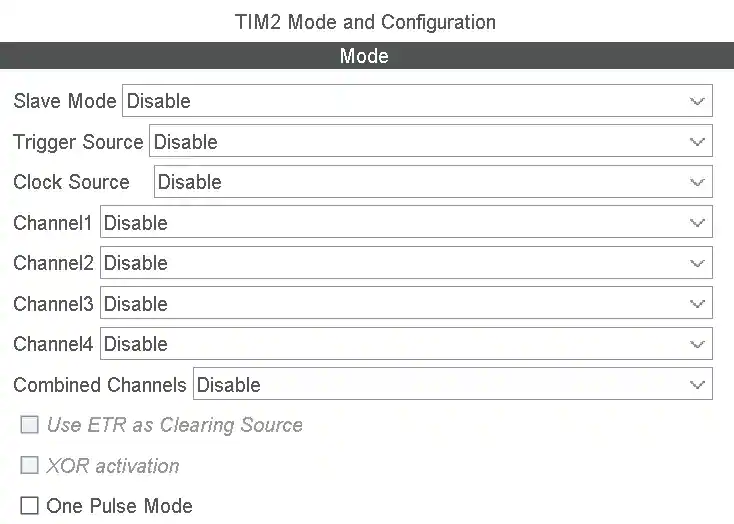
Tabs:
- Slave mode:
- Disable
- External Clock Mode 1
- Reset Mode
- Gate Mode
- Trigger Mode
- Tigger Source:
- Disable
- ITR0
- ITR1
- ITR2
- ITR3
- ETR1
- Tl1_ED
- Tl1FP1
- Clock Source:
- Disable
- Internal Clock
- ETR2
- Channel1/2/3/4:
- Disable
- Input Capture direct mode
- Input Capture indirect mode
- Input Capture tiggered by TRC
- Output Compare No Output
- Output Compare CH1/2/3/4
- PWM Generation No Output
- PWM Generation CH1/2/3/4
- Combine Channels:
- Disable
- Encoder Mode
- PWM Input on CH1
- PWM Input on CH2
- XOR ON/HALL Sensor Mode
- Use ETR as Clearing Source
- XOR activation
- One Pulse Mode
CubeMX Configuration Options Explained
Slave Mode
Sets how the current timer responds to trigger signals from other timers or external pins.
Disable: Disable slave mode. Timer runs independently, controlled only by its own control registers.External Clock Mode 1: External clock mode 1. Counter CNT is no longer driven by internal clock but by edges of the selected trigger source (such as TIx or ETR). Commonly used for “external pulse counting”.Reset Mode: Reset mode. When a rising edge appears on the selected trigger signal, the CNT counter immediately clears and restarts counting. Commonly used for “clearing counter” or “synchronizing phase”.Gate Mode: Gate mode. When trigger signal is high, CNT counts normally; when signal is low, CNT stops counting. Commonly used for “measuring high-level duration”.Trigger Mode: Trigger mode. Counter starts running on the rising edge of the trigger signal. Note: After starting, the counter runs until manually stopped. Commonly used for “delayed start”.
Trigger Source
Determines what triggers the above “slave mode” action.
ITR0/1/2/3: Internal trigger input. Sourced from other timers’ TRGO output. Specific correspondence needs to check the chip manual’s TIMx internal trigger connection table. Commonly used for “timer cascading (master-slave mode)”.ETR1: External trigger input. Signal enters through external pin ETR, goes through polarity, prescaler, and filter as trigger source.TI1_ED: Channel 1 edge detection. Both rising and falling edges of TI1 generate triggers.TI1FP1 / TI2FP2: Filtered channel signal. Signals from input pins CH1/CH2 after filtering and polarity selection.
Clock Source
Determines the pulse source for counter CNT counting.
Internal Clock: Internal clock. Default option, uses the internal clock signal processed by the APB prescaler.ETR2: External clock mode 2. Uses ETR pin as clock source. Differs from External Clock Mode 1 in that ETR2 uses a dedicated path without occupying the slave mode controller.
Channel 1/2/3/4 (Channel Mode)
Input Capture direct mode: Direct input capture. Physical pin CHx signal is connected to corresponding CCRx register. Used for “frequency measurement” or “pulse width measurement”.Input Capture indirect mode: Indirect input capture. Physical pin CHx signal is connected to adjacent CCRy register (e.g., CH1 connects to CCR2). Commonly used for “PWM input mode”, where one pin signal measures both period and duty cycle.Output Compare No Output: Output compare (no output). CNT matches CCR generates interrupt or event, but does not toggle physical pin level. Commonly used for “software timer execution tasks”.Output Compare CHx: Output compare. Toggles physical pin level on match.PWM Generation CHx: PWM output. Generates pulse width modulation signal on pin based on ARR and CCR values.
Combine Channels
Encoder Mode: Encoder mode. Uses TI1 and TI2 two-channel quadrature signals to automatically increment/decrement CNT. Used for “motor speed measurement” or “rotary knob position detection”.PWM Input on CH1/2: PWM input mode. Automatically occupies two capture registers, one measures period, one measures duty cycle.XOR ON/HALL Sensor Mode: XOR/HALL sensor mode. XORs CH1/2/3 inputs and connects to trigger controller. Commonly used for “brushless DC motor (BLDC) commutation control”.
Other Checkbox Options
Use ETR as Clearing Source: Use ETR as clearing source. When ETR signal is high, forces output reference signal (OCxREF) to clear. Commonly used for “overcurrent protection”.XOR activation: XOR activation. Enables XOR logic between channels.One Pulse Mode: One pulse mode. Counter automatically stops after one overflow (update event) occurs (OPM bit in CR1 register is set).
PWM Generation Options Explained
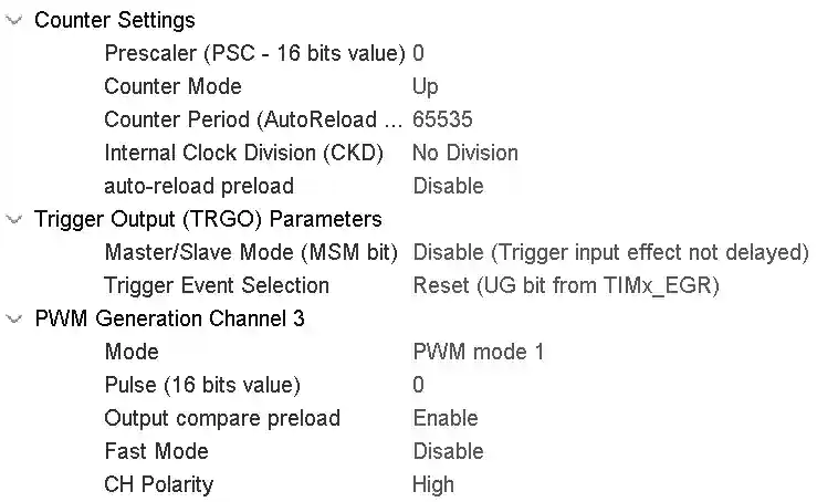
1. Clock and Counting Reference (Determines PWM Frequency)
| Config Item | Purpose | Key Formula/Logic | Typical Setting |
|---|---|---|---|
| TIMx_CLK | Timer core clock source | TIMx_CLK = APBx_CLK × (APB prescaler ≠ 1 ? 2 : 1) | Check clock tree, F103 typically 72MHz |
| Prescaler (PSC) | Divides timer clock | Count frequency = TIMx_CLK / (PSC+1) | Set PSC so count frequency ≈ 1MHz (balance of precision and range) |
| Counter Period (ARR) | Determines PWM period (frequency) | PWM frequency = count frequency / (ARR+1) | Calculate based on target frequency: ARR = (count frequency/target frequency) - 1 |
| Counter Mode | Counting direction | Up (0→ARR), Down (ARR→0), Center | Motor control commonly uses Up, three-phase drive uses Center |
| auto-reload preload | ARR update mode | Enable: ARR modification takes effect on update event; Disable: takes effect immediately | Recommend Enable to avoid waveform glitches during frequency adjustment |
2. PWM Output Control (Determines Waveform Shape)
| Config Item | Purpose | Key Logic | Typical Setting |
|---|---|---|---|
| Pulse (CCR) | Determines PWM duty cycle | Duty cycle = CCR / (ARR+1) | When dynamically adjusting duty cycle, directly modify this value |
| Mode | PWM operating mode | PWM mode 1: CNT<CCR active; PWM mode 2: CNT≥CCR active | Choose based on hardware “active level”, commonly mode 1 |
| CH Polarity | Channel polarity | High: active level is high; Low: active level is low | Match driver circuit (e.g., high-level driver motor selects High) |
| Output compare preload | CCR update mode | Enable: CCR modification takes effect on update event; Disable: takes effect immediately | Recommend Enable to avoid glitches when adjusting duty cycle |
| Fast Mode | Fast response mode | Bypasses shadow register, forces immediate output update | Default Disable, enable only when extremely fast response needed |
3. Advanced Timer Specific (Required for Driving H-Bridge Motors)
| Config Item | Purpose | Key Logic | Typical Setting |
|---|---|---|---|
| Break Input | Brake signal input | When external brake signal is active, forces PWM output off | Connect to hardware protection circuit (e.g., overcurrent detection) |
| Dead Time | Dead time | Prevents H-bridge upper and lower switches from conducting simultaneously, sets complementary output delay | Calculate based on MOS tube switching time, typically 1~10μs |
| Complementary Output | Complementary output channel | Inverted from main channel, used to drive the other switch of H-bridge | Must be used together with main channel |
4. Key Operation Flow for Dynamic Frequency Adjustment
When real-time PWM frequency change is needed (such as stepper motor acceleration/deceleration), must follow this sequence:
1. HAL_TIM_PWM_Stop(&htim, TIM_CHANNEL_1);  // 1. First stop PWM output
2. htim.Instance->ARR = new_arr;            // 2. Update ARR (new frequency)
3. // 3. Update CCR proportionally to keep duty cycle unchanged:
   new_ccr = (new_arr + 1) * old_ccr / (old_arr + 1);
   __HAL_TIM_SET_COMPARE(&htim, TIM_CHANNEL_1, new_ccr);
4. HAL_TIM_PWM_Start(&htim, TIM_CHANNEL_1); // 4. Restart PWM
Core principle: When changing frequency, must synchronously adjust CCR, otherwise duty cycle will change abruptly, causing motor torque fluctuation or even step loss.
5. Quick Reference: Timer Selection by Type
| Type | Representative | Suitable Scenario | Note |
|---|---|---|---|
| Basic Timer | TIM6, TIM7 | Pure timebase (e.g., DAC trigger, simple delay) | No output pins, cannot directly output PWM |
| General Purpose Timer | TIM2~TIM5 | Normal PWM output, input capture, encoder | Commonly used for stepper motor drives, but no dead time function |
| Advanced Timer | TIM1, TIM8 | Three-phase motor drive, H-bridge control | Must configure dead time to prevent transistor burnout |
One-Line Summary
- PSC + ARR = Frequency (PSC sets internal clock, ARR sets period)
- CCR = Duty Cycle (duty cycle = CCR/(ARR+1))
- Polarity + Mode = Active Level Logic
- Dynamic frequency adjustment: Stop PWM → Change ARR → Proportionally change CCR → Start PWM
- Driving H-bridge requires advanced timer + dead time configuration
Tip: When configuring in STM32CubeMX, first set PSC and ARR to get target frequency, then set CCR for duty cycle, finally select polarity and mode based on hardware circuit. For advanced timers, be sure to set dead time in the “Break and Dead Time” tab.